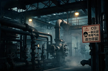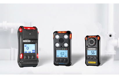












Catalyst aging, electrolyte depletion, optical window contamination… sensor drift is the biggest “hidden risk” for gas detectors. This article outlines national standard calibration intervals (6 months for catalytic, 6–12 months for electrochemical, 12 months for infrared), zero and span calibration methods, calibration gas selection and concentration calculation, calibration record management, as well as the technological trends toward calibration-free and intelligent calibration.
Gas detectors are the “safety sentinels” of chemical plants, pharmaceutical facilities, gas utilities, coating operations, and other sites. But installation is not the end of the story—regular maintenance and calibration are essential. One of the most easily overlooked aspects: sensor drift. Sensors don’t fail only when they “break”—they gradually become inaccurate.
01 | Why Do Sensors Drift?
Sensor drift falls mainly into zero drift and span drift, with core causes concentrated in four areas: sensor aging, environmental interference, circuit problems, and improper maintenance—yet throughout the entire process, the difference is rarely obvious on the instrument panel.
– Sensor aging and wear: Over long-term use, component performance declines and sensitivity degrades, or irreversible damage is caused by exposure to high gas concentrations—this is the most common cause. In catalytic combustion sensors, the catalyst bead operates at high temperature for extended periods, and the catalyst gradually ages and sinters. In electrochemical sensors, the electrolyte is continuously depleted and the electrodes become progressively passivated. In infrared sensors, the windows and mirrors in the optical path become contaminated by dust, oil, and moisture, attenuating the infrared light intensity.
– Environmental interference: Abrupt temperature and humidity changes, dust and oil covering the probe, and corrosive gas deposition all undermine detection stability—this is also the core reason for large data deviations between summer and winter.
– Circuit and power supply issues: Unstable supply voltage or temperature-induced resistance fluctuations can cause zero-point offset in the circuit.
– Improper maintenance and installation: Long overdue calibration, inappropriate installation location, insufficient aging time before calibration, and other operational issues continuously induce drift.
02 | Calibration Intervals: National Standard Requirements
National standards and metrological regulations specify clear intervals for sensors based on different principles:
| Sensor Type | Calibration Interval | Main Basis |
| Catalytic combustion (flammable gases) | 6 months | GB 12358, GB 50493 |
| Electrochemical (toxic gases / O₂) | 6–12 months | JJG 693 and other metrological regulations |
| Infrared (flammable gases / CO₂) | 12 months | Manufacturer specifications + metrological regulations |
It must be emphasized: the interval is a baseline, not a guarantee. If the environment contains silicon or sulfur compounds, or is high in humidity and dust, or if the detector alarms frequently, the interval should be shortened further; in settings with high safety integrity requirements, quarterly spot checks are also typically performed.
03 | Calibration Method: Zero + Span
Calibration is carried out in two steps, and the order cannot be reversed. Zero calibration eliminates baseline error, while proper span calibration corrects detection deviation across the instrument’s full range.
Step 1: Zero Calibration
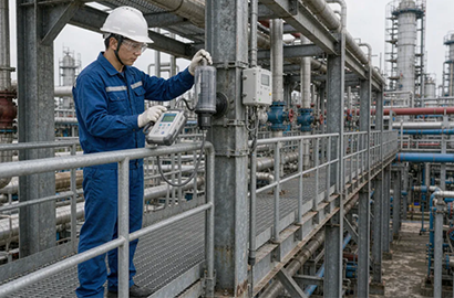
In clean air or pure nitrogen, adjust the sensor output to zero. If the target gas is present on site, cylinder nitrogen must be used to “zero” the instrument—air cannot be used as a substitute.
Step 2: Span Calibration
Introduce a standard gas of known concentration, and once the reading stabilizes, calibrate the displayed value to the standard value.
The proper procedure is “zero first, then span”: after span calibration, recheck the zero point, and repeat this cycle two to three times until both zero and span fall within tolerance. The error between the displayed value and the actual concentration must be ≤ ±3%.
04 | Selection and Concentration Calculation of Calibration Gas
Calibration gas is the “ruler” for calibration—choose the wrong ruler, and the calibration is as good as useless.
Gas type: Use a certified reference material of the same gas species as that measured by the gas detector. For flammable gases, methane or propane is commonly used; if the gas species is not specified, isobutane or propane reference material may be used. For toxic gases, use the corresponding standard gas, such as CO, H₂S, or SO₂.
Balance gas: For catalytic sensors calibrated with methane or propane, air is used as the balance gas; for electrochemical toxic gas sensors, nitrogen is typically used as the balance gas, and the manufacturer’s instructions must be followed.
Concentration value: Set according to the verification regulation for the gas being detected. For flammable gases, for example, reference materials at 40% and 60% of full scale are generally used—this avoids both the low-end nonlinear region and high-concentration shock to the sensor. When in use, the concentration units of the reference material should be converted to match the units displayed by the instrument under test.
Flow rate and temperature/pressure: Flow rate should generally be controlled at 200–500 mL/min, and the gas chamber should be fully purged before calibration.
05 | Calibration Records: Traceability and Documentation
A qualified calibration must leave a traceable record. The record includes: detector number, installation location, sensor type, calibration date, calibration gas name and concentration, cylinder batch number and expiry date, ambient temperature and humidity, readings before and after calibration, tolerance determination, calibrator’s signature, and other information.
Where conditions permit, calibration certificates should be issued by institutions with CMA/CNAS accreditation; for in-house calibration, enterprises must establish a ledger and archive records by interval. In the event of an accident investigation, this record serves both as proof of compliance and as the basis for delineating responsibility.
06 | Trends: From “Periodic Calibration” to “Intelligent Calibration”
Self-diagnosing sensors: With integrated reference elements, they can determine in real time whether sensitivity has degraded and proactively trigger maintenance alerts.
Intelligent calibration: Detectors with built-in calibration curves and temperature/pressure compensation algorithms support one-click calibration and automatic identification of calibration gas, cutting calibration time from half an hour to just a few minutes.
Long-life and calibration-free designs: Optical, laser (TDLAS), and some new electrochemical sensors can last more than 5 years; combined with online self-checking, they can significantly reduce the frequency of on-site calibration.
But no matter how advanced the technology, “calibration-free” does not mean “verification-free.” Periodic functional verification and record archiving remain mandatory requirements for safety management.
For calibration and verification of Nuoan Intelligent gas detectors, please call: 0755-26826466